Introduction
DR strategies for virtual machines (VMs) on Red Hat OpenShift are essential to maintaining business continuity during unplanned outages. As organizations migrate critical workloads to Kubernetes platforms, the ability to recover those workloads quickly and reliably becomes a key operational requirement.
While ephemeral, stateless VMs have become common in cloud-native environments, most enterprise VM workloads remain stateful. These VMs require persistent block storage that can be reattached during restarts or migrations. As a result, DR for stateful VMs presents challenges that differ significantly from those addressed by earlier Kubernetes DR patterns (Spazzoli, 2024), which typically focus on stateless container-based applications.
This blog post addresses distinct requirements of stateful VMs. It begins by exploring how cluster and storage architecture choices impact failover feasibility, replication behaviour and RPO/RTO targets. It then examines the orchestration layer, showing how Kubernetes-native tooling, such as Red Hat Advanced Cluster Management, Helm, Kustomize and GitOps pipelines, govern workload placement and recovery. Finally, this blog post concludes by considering how advanced storage platforms that replicate both block storage and Kubernetes manifests can streamline the recovery process and bridge infrastructure with application-level automation.
Level setting our terminology
Before we get too far, let’s define some important terminology:
Disaster:
For the context of this discussion, the term “disaster” refers to a “loss of site.” When thinking about DR, it is always about minimizing the disruption to a business service. So, when you lose a site, you need to implement your DR plans to restore service at the alternate site as quickly and efficiently as possible.
Note: Enacting a DR plan is not just performed when a site is lost. It is commonplace to enact DR plans for individual business services when there is a failure of a major component that requires shifting individual business services to the alternate site while the failed component is restored.
Component failure:
A component failure is a failure of 1 or more subsystems that impacts a subset of business applications in your organisation. This failure mode will require you to fail over processing to either an alternate system in the primary site, or may require you to enact individual DR plans to shift processing of the business application to a secondary site.
Recovery point objective (RPO):
RPO is defined as the maximum amount of data (measured by time) that can be lost after a recovery from a disaster or failure event before data loss will exceed what is acceptable to an organisation.
Recovery time objective (RTO):
RTO is defined as the maximum amount of time that an organization can tolerate a service being unavailable. While different architecture choices will have an impact on RTO, these considerations will not be discussed in detail within this blog post.
Metro-DR versus Regional-DR:
There are two types of DR: Metro-DR and Regional-DR.
- Metro-DR is for situations where your datacenters are close enough and network performance allows for synchronous data replication. Synchronous replication comes with the benefit that you can achieve an RPO of zero
- Regional-DR is for situations where you are forced to use asynchronous replication because the datacenters are too far apart to support synchronous replication. Asynchronous replication will almost certainly have some data loss; the amount of data loss does not matter for the purposes of this blog post
Note: If your storage infrastructure does not support synchronous replication, then a Regional-DR architecture would be used for your Metro-DR.
Restart storm:
A restart storm is an event that occurs when the number of VMs that you try to restart concurrently is so large that the hypervisor and supporting infrastructure cannot cope, resulting in either no VMs being able to restart, or the VM restarts taking orders of magnitude longer than is acceptable. This may also be described as a nonmalicious denial of service attack.
Architectural approaches to business continuity
There are several approaches to achieve business continuity and DR. For a general discussion of the topic, start by reviewing the Cloud Native Disaster Recovery for Stateful Workloads (Spazzoli, 2024) whitepaper from the Cloud Native Computing Foundation (CNCF). At a high level, there are four archetypal approaches to DR represented in the following diagram (an in-depth explanation for each of these approaches is included within the whitepaper):
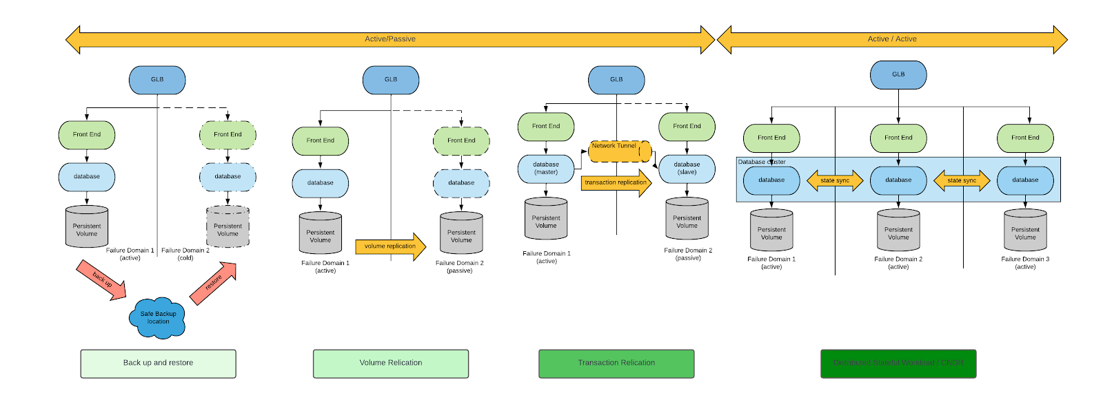
When considering DR requirements for VMs, backup and restore and volume replication are the only appropriate DR patterns.
While both backup and restore and volume replication are viable approaches, volume replication-based DR approaches minimize both RPO and RTO. For this reason, we’ll focus only on volume-replication based DR approaches.
Having narrowed down our field of analysis, we will discuss two architectural approaches to DR, which architecturally are distinguished by the type of volume replication:
- Unidirectional replication
- Symmetric replication, or bidirectional replication
Unidirectional replication
With unidirectional replication, volumes are replicated from one datacenter to another, but not vice versa. The replication direction is controlled via the storage array and the volume replication can be either synchronous or asynchronous. The choice depends on the storage array capability and the latency between the two datacenters. Asynchronous replication is suitable for datacenters that have high latency between each other and are most likely in the same geographical region of the world, but not in the same metropolitan area.
Architecturally, unidirectional replication is depicted similarly to the following figure:
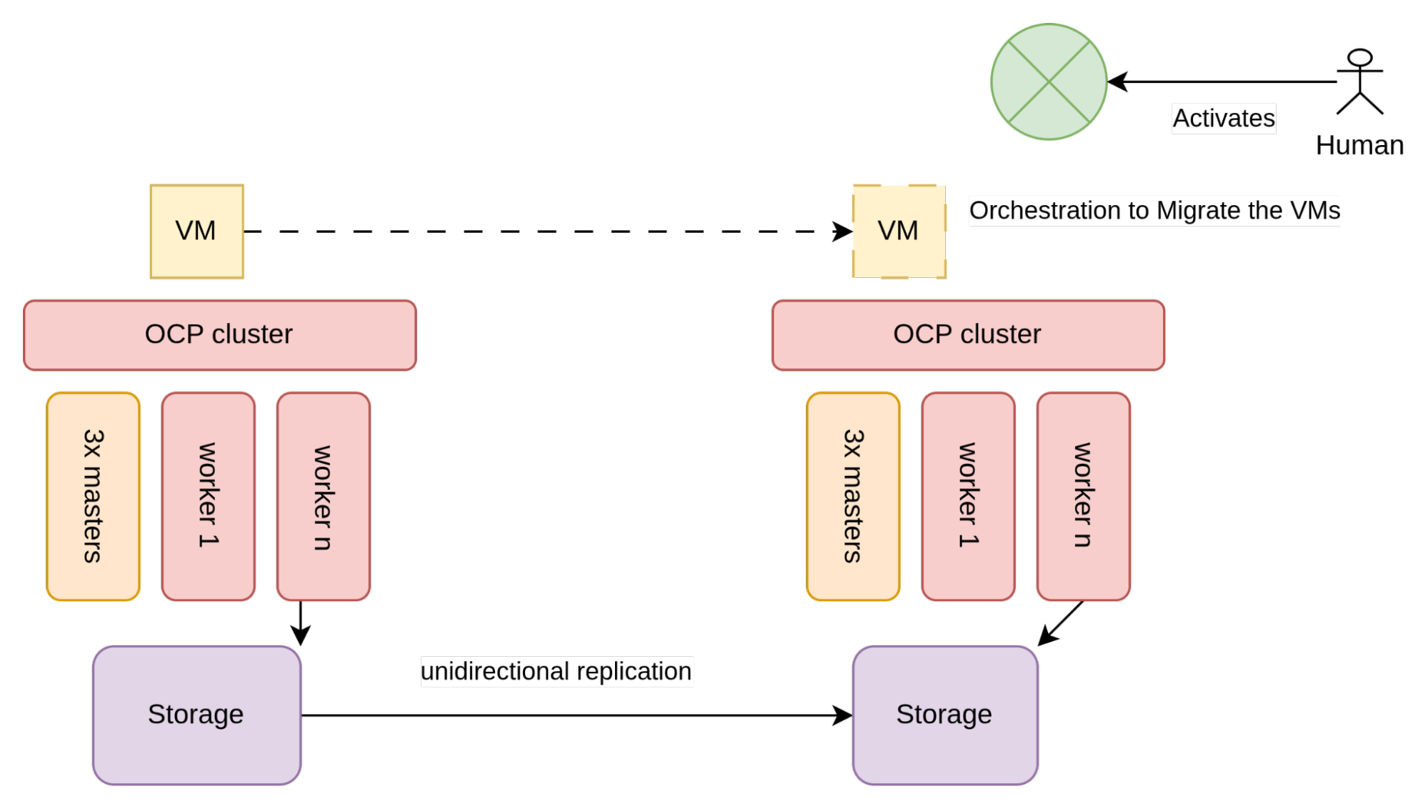
As illustrated in figure 2, storage used by the VMs (typically SAN arrays) is configured to allow for unidirectional replication.
Two different OpenShift clusters exist in each datacenter and each are connected to the local storage array. The clusters are unaware of each other, so the only constraints to implement this architecture are given by the storage vendor and specifically by the requirements that need to be met to enable unidirectional replication.
Unidirectional volume replication considerations
Volume replication is not standardized in the Kubernetes CSI specification. As a result, storage vendors have built proprietary custom resource definitions (CRDs) to enable this capability. At a high level, we are seeing vendors at three levels of maturity with this capability:
- The volume replication capability is not available at the CSI level, or it is available in a way that does not allow for the creation of a proper DR orchestration without calling the storage array API directly
- The volume replication capability is available at the CSI level
- The volume replication capability is available and the vendor also manages restoring the namespace metadata (i.e., the VMs and other manifest present in the namespace)
Given this fragmentation, it is not straightforward to write a vendor-agnostic DR recovery process for a regional DR setup. The amount that needs to be written to create a proper DR orchestration depends on the storage vendor.
Let’s examine the behavior of this architecture under different failure modes: OpenShift node failure, storage array failure (component failures) and entire datacenter failure (this is the actual DR scenario).
OpenShift node failure
In the event of a node (component) failure, the OpenShift Virtualization scheduler is responsible for automatically restarting the VM on the next most appropriate node in the cluster. No further action should be required in this scenario.
Storage array failure
If a storage array fails, all the VMs that are reliant on the storage array will also fail. In this scenario, the DR process will need to be enacted. (Refer to the Disaster Recovery Process section for the steps involved.)
Datacenter failure
During a datacenter failure, a DR process must be enacted to restart all the VMs in the datacenter not affected by the failure. Automation plays a key role here. However, the process is typically initiated by a human within a major-incident management framework. The following section provides an overview of the steps involved.
Disaster recovery process
DR procedures can become very complicated, but in simple terms, a DR process should consider the following:
- VMs that are part of the same application should have their volumes replicated in a consistent manner. This typically means that the volumes of those VMs are part of the same consistency group
- It must be possible to control whether volumes in a consistency group should be replicated and in which direction. Under normal circumstances, volumes will be replicated from the active site to the passive site. During a failover, volumes are not replicated. During the preparation phase for the failback, volumes are replicated from the passive site to the active site. During failback, volumes are not replicated
- It should be possible to restart the VMs in the other datacenter and they must be able to attach to the replicated storage volume
- VM restart might need to be throttled to avoid a restart storm. Additionally, it is often desirable to prioritize the VM restart sequence so that the most critical applications start first or to ensure that dependent components, such as databases, are started before the services that rely on them
Cost considerations
Depending on how the OpenShift cluster is configured, it might be considered a warm or hot DR site. Hot sites have to be fully subscribed, while warm sites do not (potentially allowing for some cost savings).
In general, if there are not active workloads running on the DR site, it can be considered warm. In particular, one can configure persistent volumes (PVs), persistent-volume claims (PVCs) and even non-running VMs, ready to be started in case of a disaster and still retain a warm site designation.
Symmetric active/passive
It is not a common practice to have 100% of workloads in the active site. Instead, organizations will have as much as a 50:50 split across the primary and secondary datacenters. This is a practical approach that ensures that any disaster will never take out all of the services at once. In addition, overall recovery effort is reduced accordingly.
When distributing active VMs in each datacenter, each side is configured to be able to failover to the other side. This setup is sometimes known as symmetric active/passive.
Symmetric active/passive will work with OpenShift Virtualization and the architecture that we have examined above. Just keep in mind that with symmetric active/passive, both datacenters are considered active and therefore all of the OpenShift nodes must be subscribed.
Symmetric replication
With symmetric replication, volumes are replicated synchronously and in both directions. As a result, both datacenters can have active volumes and can take writes on those volumes. For this to be possible, an organization must have two datacenters whose network latency is very low (e.g., ~<5ms). This is typically possible if the two datacenters are in the same metropolitan area, hence why this architecture is also known as Metro-DR. Under this circumstance, the following architecture can be used:
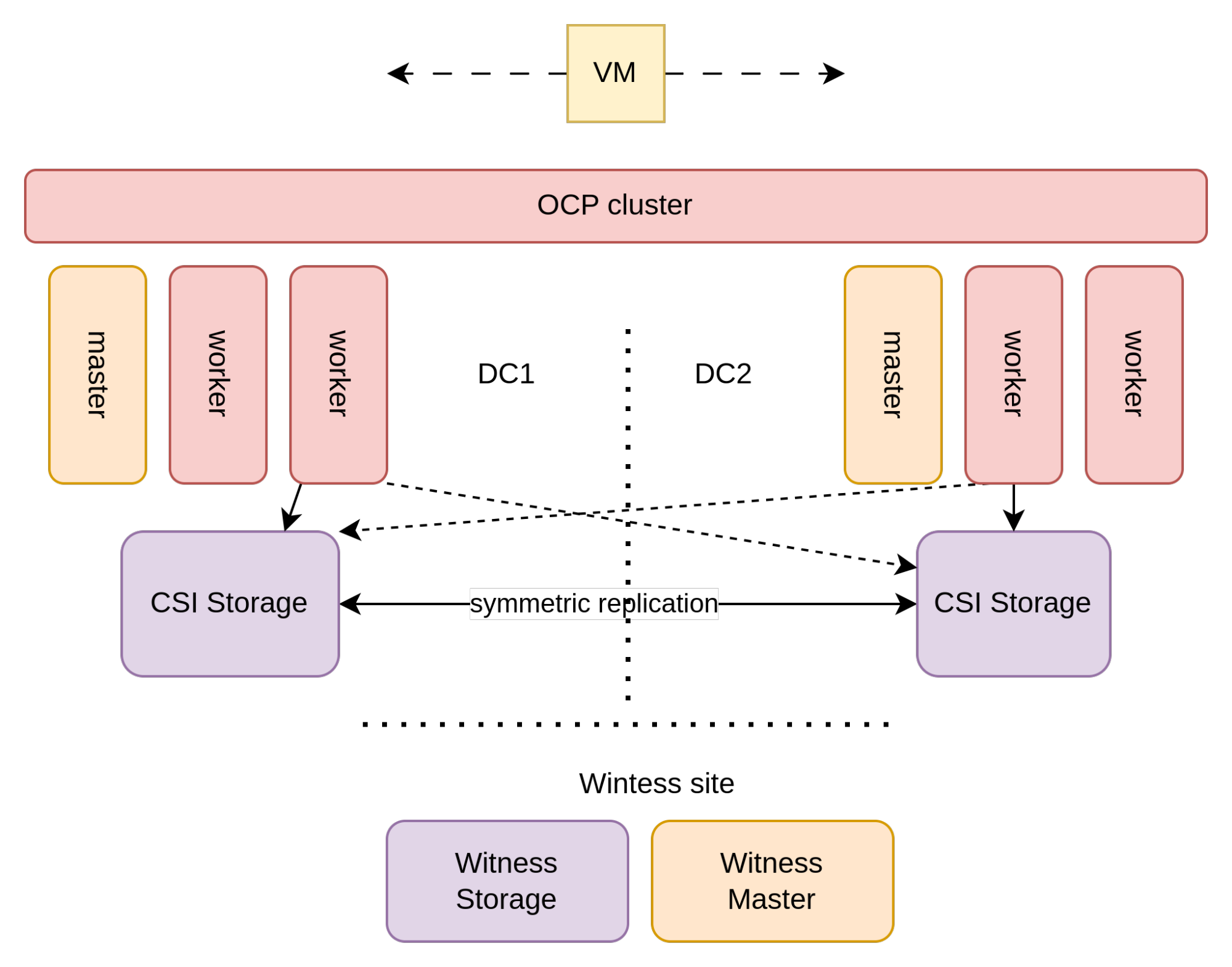
In this architecture, the storage used by the VMs (typically a SAN array) is configured to perform symmetric replication between the two datacenters.
This creates a logical storage array stretched across the two datacenters. To enable symmetric replication, it is necessary to have a “witness site” that acts as an independent arbitrator to prevent “split-brain” scenarios in the event of a network or site failure.
The witness site does not have to be as close (in terms of latency) as with the two main datacenters as it is used for creating quorum and to tie break split-brain scenarios. The witness site must be an independent availability zone, does not carry any application workloads, does not need to have a large capacity, but it should have the same quality of service of the other datacenters in terms of datacenter operations (e.g., physical/logical security, power management, cooling).
With storage being stretched across datacenters, OpenShift is stretched on top of it. To implement this in a highly-available architecture, three availability zones (sites) are required for the OpenShift control plane. This is due to the fact that the Kubernetes' internal etcd database requires at least three failure domains to maintain a reliable quorum. This is commonly implemented by taking advantage of the storage witness site for one of the control-plane nodes.
Most storage area network (SAN) vendors support symmetric replication for their storage arrays. However, not all vendors surface this capability at the CSI level. Assuming a storage vendor that supports symmetric replication at the CSI level and assuming the necessary prerequisite and configurations have been met, when a PVC is created, a multipath logical unit number (LUN) is provisioned. This LUN includes paths going to both datacenters so all OpenShift nodes must be configured to enable connectivity to connect to both storage arrays. The multipath device is typically created either with an asymmetric logical unit access (ALUA) configuration (Pearson IT Certification, 2024) (i.e., active/passive, where the active path is the one to the closest array) or with an active/active path with different weights in which the closest array has high weights.
Some vendors even allow for this architecture when the Fiber Channel connections are not “uniform,” meaning that nodes on one site can only connect to the local storage array. In this case, the ALUA configuration is, of course, not created.
This cluster topology helps protect against both component failures as well as disasters. Let’s examine the behavior of this architecture under different failure modes.
OpenShift node failure
In the event of a node (component) failure, the OpenShift Virtualization scheduler is responsible for automatically restarting the VM on the next most appropriate node in the cluster. No further action should be required in this scenario.
Storage array failure
Multipath LUNs help provide a continuity of service in the event one of the two storage arrays fails or is taken offline for maintenance. In a uniform connectivity scenario, the passive or less weighted path of the multipath LUNs will be used to connect the VM to the other arrays. This failure is completely transparent to the VMs, resulting in the potential for a slight increase of the disk I/O latency. In a nonuniform connectivity scenario, the VM has to be migrated to a node with connectivity.
Datacenter failure
When an entire datacenter becomes unavailable, this will be perceived by the stretched OpenShift as a failure of multiple nodes at the same time. OpenShift will start scheduling VMs to nodes within the other datacenter as described in the OpenShift node failure section.
Assuming there is enough spare capacity for workloads to migrate to, all machines will eventually restart in the other datacenter. VMs that have restarted have exactly zero RPO and a RTO given by the sum of the following times:
- The time it takes OpenShift to realize that nodes are in an unready state
- The time it takes to fence the nodes
- The time it takes to restart the VMs
- The time it takes to complete the VM boot process
This DR mechanism is essentially fully autonomous and does not require human intervention. This may not always be desirable. To avoid a restart storm, it is often desirable to control which VMs are restarted and when this process is initiated.
Metro-DR considerations
The following are some of the considerations regarding this approach:
- Because VMs typically are connected to VLANs, for them to be able to float between datacenters, it is necessary that VLANs are also stretched between the metro datacenter. In some cases, this can be undesirable
- Often, the witness site management network (OpenShift node network) is not in the same L2 subnet as the management network of the metro datacenters
- Some schools of thought do not consider this a full DR solution as the OpenShift control plane and storage array control plane are two single points of failure (SPOF). This SPOF is intended in a logical sense, as from a physical perspective, of course, there is redundancy. However, it is true that a single mistaken command to either OpenShift or the storage array can, in theory, wipe out the entire environment. For this reason , this architecture is sometimes daisy-chained to a more traditional regional DR architecture for the most critical workloads
- Left to its own devices, during a DR situation, OpenShift will automatically reschedule all the VMs in the datacenter affected by the disaster at the same time to the healthy datacenter. This might cause a phenomenon known as a restart storm. There are a number of Kubernetes features that will mitigate this risk by controlling which applications fail over when. The concept of restart storms will be discussed in later sections
Cost considerations
With symmetrics replication, both sites must be fully subscribed as they belong to a single active OpenShift cluster. As for unidirectional replication, each site must be 100% overprovisioned, allowing for a failover of 100% of the other site.
Conclusion
The decision between unidirectional and symmetric replication architectures sets the stage for the entire DRstrategy on OpenShift Virtualization. Each model comes with trade-offs between operational complexity, infrastructure cost, RPO/RTO guarantees and automation potential. Whether you choose a dual-cluster or stretched-cluster design, the foundational architecture must align with business continuity expectations and infrastructure constraints. With this groundwork in place, Part 2 shifts the focus from infrastructure to orchestration—moving beyond storage to examine how VMs are placed, restarted and controlled under disaster conditions.
product trial
Red Hat OpenShift Virtualization Engine | Testversion
Über die Autoren

Bryon is a skilled infrastructure and software engineering specialist with deep expertise in AI/ML, Kubernetes, OpenShift, cloud-native architecture, and enterprise networking. With a strong background in storage technologies, infrastructure, and virtualisation, Bryon works across domains including system administration, AI model deployment, and platform engineering. He is proficient in C#, Golang and Python, experienced in container orchestration, and actively contributes to Red Hat-based solutions. Passionate about education and enablement, Bryon frequently develops technical workshops and training programs, particularly in AI/ML and DevOps. He is also a practising musician, blending his technical acumen with creative expression.

Raffaele is a full-stack enterprise architect with 20+ years of experience. Raffaele started his career in Italy as a Java Architect then gradually moved to Integration Architect and then Enterprise Architect. Later he moved to the United States to eventually become an OpenShift Architect for Red Hat consulting services, acquiring, in the process, knowledge of the infrastructure side of IT.
Currently Raffaele covers a consulting position of cross-portfolio application architect with a focus on OpenShift. Most of his career Raffaele worked with large financial institutions allowing him to acquire an understanding of enterprise processes and security and compliance requirements of large enterprise customers.
Raffaele has become part of the CNCF TAG Storage and contributed to the Cloud Native Disaster Recovery whitepaper.
Recently Raffaele has been focusing on how to improve the developer experience by implementing internal development platforms (IDP).
Mehr davon
Nach Thema durchsuchen

Automatisierung
Das Neueste zum Thema IT-Automatisierung für Technologien, Teams und Umgebungen

Künstliche Intelligenz
Erfahren Sie das Neueste von den Plattformen, die es Kunden ermöglichen, KI-Workloads beliebig auszuführen

Open Hybrid Cloud
Erfahren Sie, wie wir eine flexiblere Zukunft mit Hybrid Clouds schaffen.

Sicherheit
Erfahren Sie, wie wir Risiken in verschiedenen Umgebungen und Technologien reduzieren

Edge Computing
Erfahren Sie das Neueste von den Plattformen, die die Operations am Edge vereinfachen

Infrastruktur
Erfahren Sie das Neueste von der weltweit führenden Linux-Plattform für Unternehmen

Anwendungen
Entdecken Sie unsere Lösungen für komplexe Herausforderungen bei Anwendungen
Virtualisierung
Erfahren Sie das Neueste über die Virtualisierung von Workloads in Cloud- oder On-Premise-Umgebungen